The Front Panel Connectors, or the Front Panel Header, or FPanel, is a block of connectors on a motherboard that controls the power on, power reset, beep code speaker, and the LED light indicators on your PC case/chassis.
All motherboards have front panel connectors that a PC case connects to. The cables that connect to the motherboard come from the PC case.
In the following text, we will discuss in detail what Front Panel Connectors look like, what they do, and how they connect to the PC case.
TABLE OF CONTENTS
What are Front Panel Connectors?
As mentioned, Front Panel Connectors connect the PC Case’s Power Switch, Reset Switch, and LED indicators to the motherboard.
Front Panel Connectors consist of small pins that serve a specific electrical purpose. For instance, for the Power Switch, there are two specific pins for connecting the case’s cable.
Similarly, there are two specific pins for the reset switch as well.
As mentioned earlier, there are five primary functions that almost ALL Front Panel Headers have:
- Power Switch Pins – Abbreviated as PWRSW or simply PW – are two pins connecting to the Power Button cable from the PC case.
- Reset Switch Pins – These are two pins connecting to the PC case’s reset switch.
- Power LED Pins – These are three pins that connect to the LED light on the PC case, indicating whether the PC is on, off, or in sleep mode.
- Hard Disk LED Pins – These are two pins that indicate the activity of the hard disk by flashing repeatedly.
- Speaker Pins – are four pins for the beep code speaker. Many PC Cases come with a beep code speaker. Note that a beep code speaker is NOT the same as a stereo speaker.
However, as you will see below, certain Front Panel Headers can have more than just the five functions mentioned above.
Also Read: What are USB Headers?
What Do Front Panel Connectors Look Like?
The following image shows a typical block of front panel connectors.
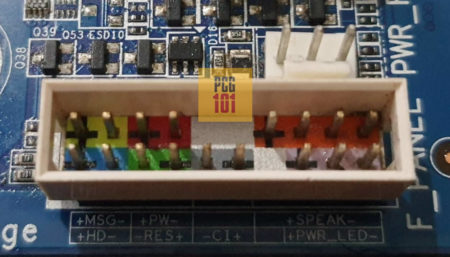
As you can see, it consists of several pins, each with a specific purpose.
The Front Panel Connectors may not have a block encasing some motherboards.
How To Locate the Front Panel Connectors?
The location of the Front Panel Connectors is pretty straightforward. You can use two methods:
- Use the Motherboard Manual
- Read the Labels Physically On the Motherboard
1. Using The Motherboard Manual
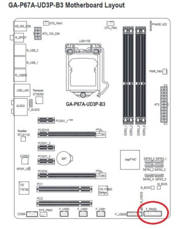
The manual often has a complete diagram indicating the location of various sockets, slots, and connectors on the motherboard.
For instance, the following image shows the location of the Front Panel Connectors on my motherboard, Gigabyte GA P67A UD3:
Again note that the Front Panel Connectors may be called Front Panel Header on some motherboards. They are essentially the same thing, just different names.
Also Read: How Difficult is it To Build a PC?
2. Read the Labels Physically On the Motherboard
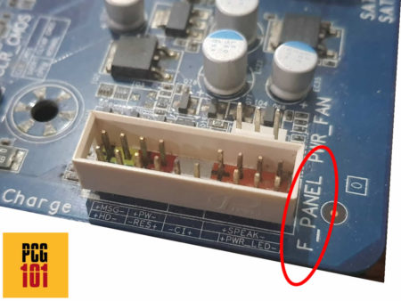
Like the Front Panel Connectors, all motherboards have labels next to connectors or sockets.
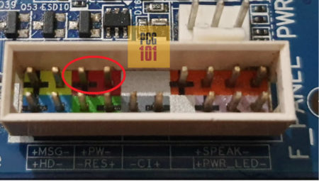
For instance, the Front Panel Connectors are highlighted on my motherboard with the label “F_Panel.”
How to Know Which Pins to Use for What?
Again there are two ways to figure this out. Either you read the physical labels for each pin of the Front Panel Header on the motherboard, or you consult the motherboard manual.
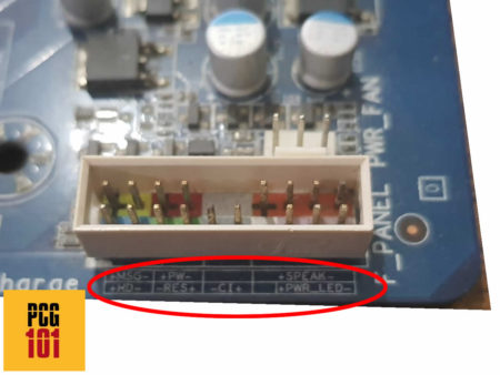
The following image shows the labels indicating the function of the pins on my F_Panel.
The following image shows the same pins but on the motherboard’s manual:
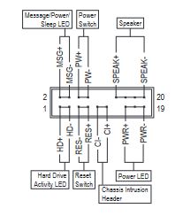
It is important to consult your motherboard about what the physical labels indicate because some unique connectors, such as my motherboard has above, can confuse you.
For instance, my F_Panel also has pins for the following functions, along with the specific positions I mentioned above already:
- + MSG – Message LED (Message/Power/Sleep LED, Yellow/Purple LED) – Indicates PC’s power status.
- + CL – Chassis Intrusion Header (Gray LED) – Detects if the PC Case cover is removed. This requires a PC case that has a specific chassis intrusion sensor.
It would be best to connect the cables from the PC case to the correct pins. The following image shows two pins on my F_Panel that would connect to the Power Switch button.
The Cables Come with the PC Case
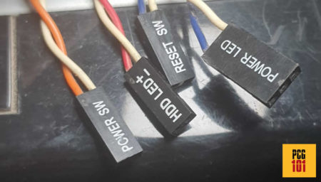
The cables that connect to the Front Panel Connectors come with the PC case.
My PC case comes with the following cables:
Your PC case may not have ALL the PC cables. Therefore, you DO NOT have to populate all the pins on the Front Panel Connectors.
For instance, if your PC case is missing a beep code speaker, as mine does, it may not have a cable.
Similarly, if your PC case lacks a Chassis Intrusion sensor, the Chassis Intrusion Pins (+CL- on my motherboard) would be left empty.
The next step is to plug the cables into the correct pins:
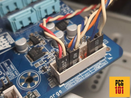
The Orientation of Certain Cable Connections do Matter
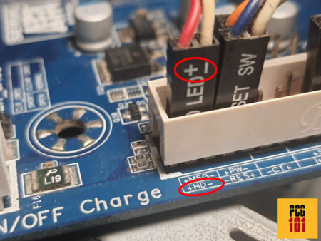
For LED light connectors, particularly, the orientation of the connection matters.
In other words, you must ensure you connect the + terminal of the cable to the + pin and the – terminal to the – pin.
Take the following Hard Disk LED cable, for instance. Here the red cable indicates the + terminal, and the white cable shows the – terminal.
You must align that with the orientation shown on the front panel label.
For Power and Reset switch, the orientation of the cable DOES NOT matter.
Also Read: What is the Difference Between System Fan and CPU Fan?
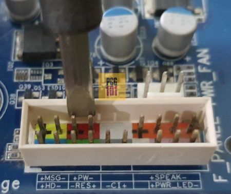
The Front Panel Power Connectors can be Used to JUMP the Motherboard
One essential function the Front Panel Connectors provide is the ability to jump-start the motherboard in case you do not have a power-on button.
With a precision screwdriver, touching both the Power On Switch pins together would Power On your PC.
Also Read: How to Reset Motherboard? – Clearing CMOS
You Can Buy a Spare Beep Code Speaker for the Speaker Pins
As mentioned, all Front Panel Connectors have pins that support a Beep Code speaker. Most PC cases do come with a Beep Code speaker.
If your PC case does not, you can buy one separately and connect it to the corresponding front panel connectors.
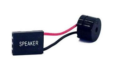
A beep code speaker, aka motherboard speaker or PC speaker, is an important troubleshooting tool for your PC hardware.
Also Read: How to Connect Motherboard Internal Speaker?
The number of beeps it makes indicates where a specific problem lies in the hardware.
For instance
- One beep suggests a problem with the RAM
- Four beeps indicate a particular problem with the motherboard
- Five beeps indicate issues with the CPU, and so on.
You can find a complete list of beep codes and what they mean here.
Also Read: What are Motherboard Power Phases?
Final Words
While the Front Panel Connectors may seem trivial initially, they are the primary channel through which the system and buttons on the case/chassis communicate with the motherboard.
Among the most important function it offers is the Power On Switch for the case button to connect to.
You must consult the motherboard manual for details regarding the different pins on your front panel connectors.
Also Read: Why Do Motherboards Still Have PS2 Ports?
frequently asked questions
1. What are the different pins on a front panel connector, and what do they do?
Front panel connectors typically have a set of pins that connect to specific functions, including the power button, reset button, HDD LED, power LED, and speaker.
The exact configuration of the pins can vary between motherboards, but the most common pin configurations include two pins for the power button, two pins for the reset button, two pins for the HDD LED, two pins for the power LED, and two pins for the speaker.
The pins are usually labeled on the motherboard to help identify which function they correspond to.
2. What happens if I connect the front panel connectors incorrectly?
If you connect the front panel connectors incorrectly, the computer may not start up or may exhibit unexpected behavior.
For example, if you connect the power LED to the reset button pins, the LED may flash when you press the reset button instead of when the computer is turned on.
To avoid these issues, it is important to carefully read the motherboard manual and double-check the pin configurations before connecting the front panel connectors.
3. Can I use a splitter or adapter to connect multiple front panel connectors to a single header?
Yes, you can use a splitter or adapter to connect multiple front panel connectors to a single header on the motherboard.
However, it is important to ensure that the total power draw of the connected components does not exceed the maximum capacity of the header.
Additionally, using a splitter or adapter may cause issues with the proper functioning of the front panel connectors, such as misaligned LEDs or button presses that do not register.
4. Are front panel connectors standardized across different motherboard brands and models?
While the functions of front panel connectors are standardized across most motherboards, the exact pin configurations and layout can vary between brands and models.
Therefore, it is important to consult the motherboard manual or documentation to identify the specific pin layout for your motherboard’s front panel connectors.
Some motherboard manufacturers also provide specialized adapters or front panel connectors that are designed to work with their specific motherboard models.
Thank you for the post, God bless you, Amin.
Everything I wanted I got it and I was impressed thank you
Got everything I needed thank you