An internal motherboard speaker, a beep code speaker, a system speaker, or a buzzer is essential in identifying and troubleshooting a hardware issue with your PC. But if you are new to PC building, you can get confused about properly connecting the motherboard’s internal speakers.
An internal motherboard speaker needs to connect to their designated connectors found on the motherboard. These will be pretty easy to spot, often with four pins sticking out.
The connectors for the internal motherboard speaker are often labeled as “SPEAKER” or “SPK” and can be found close to the Front Panel Connector.
To find the exact location of where the connectors for the internal speaker, you will have to refer to the motherboard’s spec sheet.
I will discuss how to connect the motherboard’s internal speaker and connect the motherboard beep code speaker in the following text.
TABLE OF CONTENTS
Types of Beep Code Speakers
While all beep code speakers serve the same function, you may find them in two popular physical profiles.
Large Profile Dynamic Speakers
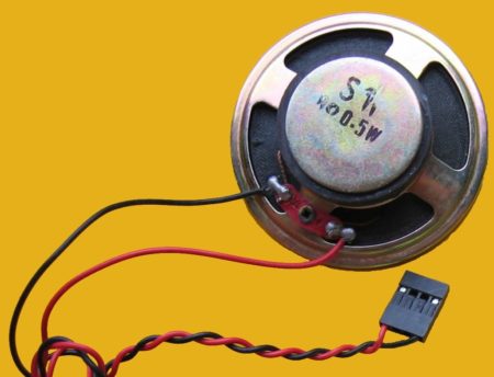
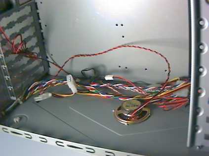
These prominent motherboard speakers have more or less been phased out. They were based on dynamic design and were often found in cases.
If you have a beep code speaker that came with a case, then chances are it is a prominent dynamic speaker.
Finding a PC case with a built-in beep code speaker is almost impossible.
These days you have to buy the motherboard’s internal speaker separately.
Tiny Moving Iron Speaker
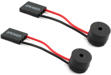
Tiny speakers, as shown above, are the internal speakers used these days on motherboards.
They are small, cheap, do not take up precious space inside the motherboard chassis, and perform the same function as their larger counterparts.
Most of the time, these do not come with the case or the motherboard. You have to procure these separately on your own. Luckily they do not cost more than a dollar.
How to Connect a Motherboard’s Internal Speaker?
There are three basic steps to connecting the motherboard’s internal speaker:
- Locating the Beep Code Speaker Connector On the Motherboard
- Taking Note of the Polarity (Orientation of How You Plug in)
- Aligning the Positive Terminal Of the Speaker with Speaker+ Pin on the Motherboard
Step 1: Locating the Beep Code Speaker Connector On the Motherboard
Standard motherboard speakers have a 4-pin connector.
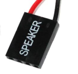
They must be connected to the four corresponding pins on the motherboard.
Therefore, to connect the motherboard’s internal speakers, you must first locate where they need to go on the motherboard.
Locating the Motherboard Speaker Connectors Through Physical Inspection
You can often find the exact location of the four pins designated for the beep code speaker by visually inspecting the motherboard.
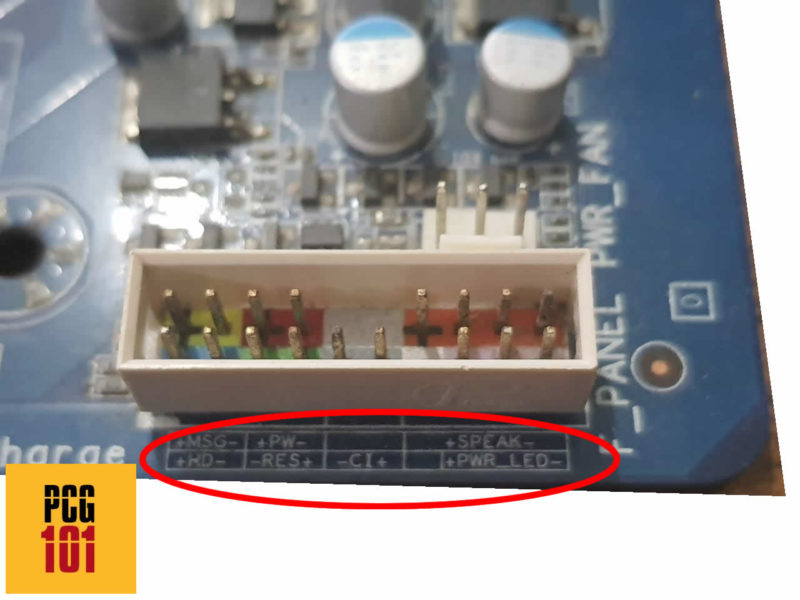
Most, if not all, motherboards have the pins for the internal speaker clearly labeled. The pins for the internal speaker are often located either inside the front panel header or right next to it.
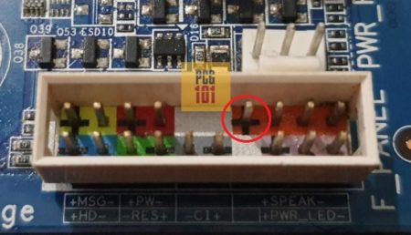
Take, for instance, my motherboard (Gigabyte GA P67A UD3). In my motherboard, the four pins for the speaker are located in the Front Panel Connector.
Locating the Speaker Connectors Through Manual
It is also highly advisable to refer to your motherboard’s manual to find the exact location of its internal speaker connectors.
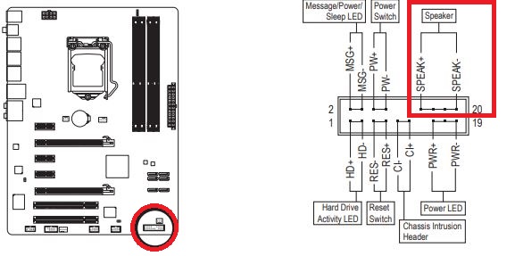
For instance, the image above is an excerpt from my motherboard’s manual. It shows you the location of 4 pins intended for the internal speaker. So here, pins #14, 16, 18, and 20 correspond to the motherboard speaker.
Step 2: Taking Note of the Polarity (Orientation of How You Plug in)
An essential aspect to look out for is the polarity of the Pins. You have to make sure that the orientation of the beep code speaker’s connector aligns with the CORRECT pins on the motherboard.
In other words, you have to connect the + terminal of the speaker to the positive pin on the motherboard and the – terminal to the negative pin.
The best way to figure out which pin on the motherboard is harmful and which is positive is to refer to the manual again, particularly the pinout diagram.
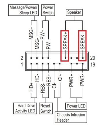
Pin #14 is +. Pin #20 is -.
- The Positive pin is often labeled as SPEAK+ or VCC (#14 in this case)
- The Negative pin is labeled as SPEAK- (#20 in this case)
Hence on my motherboard, pin #14 corresponds to where I would connect the positive terminal of the beep code speaker, and pin #20 is where I would join the negative terminal.
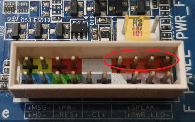
Often, motherboards have signs, labels, and indicators identifying the positive terminals for you by physical inspection.
For instance, the positive terminal has a + sign inscribed on my board.
Step 3: Aligning the Positive Terminal Of the Speaker with Speaker+ Pin
The final step in connecting the motherboard’s internal speaker is plugging in the right side of the speaker’s connector to the correct pins.
The following graphics illustrate how to align the motherboard’s internal speaker’s connector with the pins:
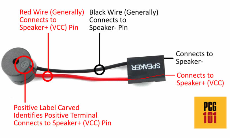
A few key points to note:
- Motherboard speakers have a positive sign (+) carved on top indicate, ing which terminal/wire connects to the Speaker+ or VCC pin on the motherboard.
- Red wire generally, and as per electrical standards, connects to the positive side, i.e., to the Speaker+ (VCC) pin.
- Black wire generally, and as per electrical standards, connects to the negative side or the Speaker- pin.
- While there are four pins and four connectors, only the two on the ends matter. The two in the center have no connection.
Also Read: How to Test Motherboard Without CPU?
Beep Codes and Troubleshooting
A motherboard speaker is essentially a tool for troubleshooting issues with your hardware.
Once you have installed the speaker correctly, restart your PC. It will sound short beeps if it detects any issues on startup and during POST.
The amount of beeps and their duration indicates where the issues lie. For instance
- One short beep: issues with RAM
- FiveFive short beeps: problems with CPU
- One long beep, two short beeps – issues with Graphics Card
Here is a list of all the beep codes and what they mean.
Also Read: How to Reset Motherboard?
FREQUENTLY ASKED QUESTIONS
1. Does Motherboard Speaker Come with the Motherboard or the PC?
You can find the beep code speaker built on the motherboard or inside the PC case in sporadic instances.
However, generally, you have to buy one yourself separately.
2. Can Motherboard Speaker Play Audio/Music?
No, it cannot. Internal motherboard speakers cannot generate complex sounds.
Back in the early days (the 90s), it was used for very simple-sounding polyphonic music and sound effects for games.
But essentially, you cannot play any audio from these speakers. No setting in the OS allows you to switch to the internal speaker for audio.
3. How to Connect Two-Pin Two-Wire Internal Speaker?
In some rare instances, you may have encountered internal speakers with two wires with one pin each.
Here, you would use the same principle as in Step 3 above.
The speakers have the + Sign engraved, corresponding to the positive wire. You will connect this to the Positive Speaker+ (Vcc) pin and the other to the Negative Speaker- pin on the motherboard.
The rest of the two pins in between can be left unconnected.
More Guides:
It appears that modern motherboards are disabling the beep function. I have a B450M motherboard with the proper connector but the moving iron speaker I have attached to it does not beep at all. I can’t force it to beep. So, why are MB makers providing a marked 4-pin “speaker” connector if it is non-functional?